Toyota A340E Transmission
Wiring up the A340E to SMART 150 TCM
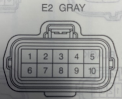
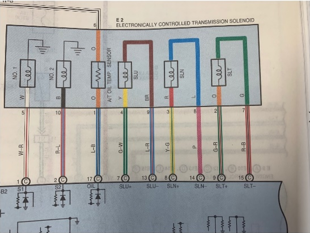
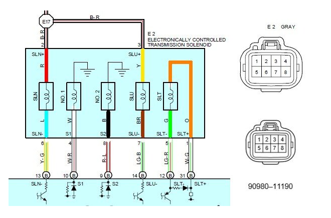
· Shift solenoid #1 – Solenoid A output (Yellow)
· Shift solenoid #2 – Solenoid B output (Brown)
· SLU solenoid (lockup) – Solenoid C output (Green)
· SLT solenoid (pressure control) – Solenoid D output (Blue)
· SLN solenoid (accumulator) – NOT USED
· Speed sensor #1 (VSS) – Vehicle speed input (Pink)
o Vehicles with cable speedometer have VSS speed signal in cluster
o Vehicles with electronic speedometer VSS is on the right rear of trans
o Speed sensor #2 may be used instead (left rear of trans) but does require the use of a VR-Hall signal converter to be compatible
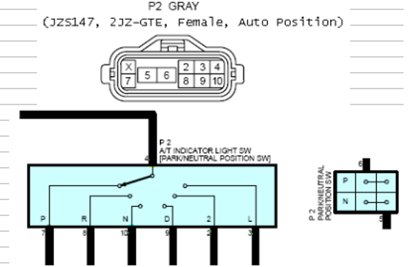
· Range switch – reverse signal required for proper reverse engagement. Either connect only the reverse pin to a digital input or use our SMART PRND module to connect all positions to the AI2 input
Diagrams:


